| Home Page | Refurbish Home Page | Refurbish #1 | Updatemydynaco Store |
|---|
Customers have been kind enough to send pictures of their handiwork. We're happy to show them here.
John mixed together Updatemydynaco modules, the Van Alstine Power Supply Mod, and lot of extra capacitance in the form of Dynamite Capacitor Configurations, plus some extra capacitance. Here are the pictures he sent along.
Although they're shown at small size, the resolution is still pretty good. To see a bigger version of these pictures, just (in Firefox) right click on a photo and select "View Image". It will open a the small photo as a 480x640 window. Just hit the back key to get back to the photos.
John thought you'd like to see these pictures in greater detail. If so, you can download these pdf's:
Mike had an interesting story about the history of his 120, which he has been kind enough to share with me.
" I have recently finished "upgrading" my Dynaco Stereo 120 with your parts and am pleased with the results. Calling the process an upgrade is ridiculous, of course. It's a completely new design now with only the transformer and one power supply capacitor left over from the Stereo120. Have you considered supplying a decal or sticker to cover the Dynaco name? That would be a nice touch.
The project was something more than a simple matter of parts replacements. As I removed the Dynaco parts I couldn't help thinking of assembling the amp over 45 years ago and its subsequent history. I bought it May 16, 1967, paying $154.68. That's over $1000 today and it wasn't anywhere near as good as what $1000 will buy today.
The Stereo 120 reliability was not so good either. The first trouble started in October 1967 with Dynaco replacing 6 transistors and 2-TW-15, what ever it/they is/are. In late '75 an amplifier test clinic at a local dealer revealed it was a 100 watt amp. In 1976 it started injecting RF into the power lines, which was not cured by capacitors across the rectifier diodes. So, Dynaco got it again, replacing 4 capacitors, a resistor and a diode (D1). On top of that, I had to return it for re servicing. I forget why. I see in my notes that it received a replacement for C4, left channel in December '81, only to fail big time a few weeks later, receiving 5 transistors and a diode at a local shop.
Sometime after that, it went into semi retirement, being used for TV audio at times. By this time, I was knowledgeable and confident enough to handle its next problems myself. In April 2003, I replaced Q9 and C3. It held out until February 2012 when I replaced Q9 again along with R23. Whew!
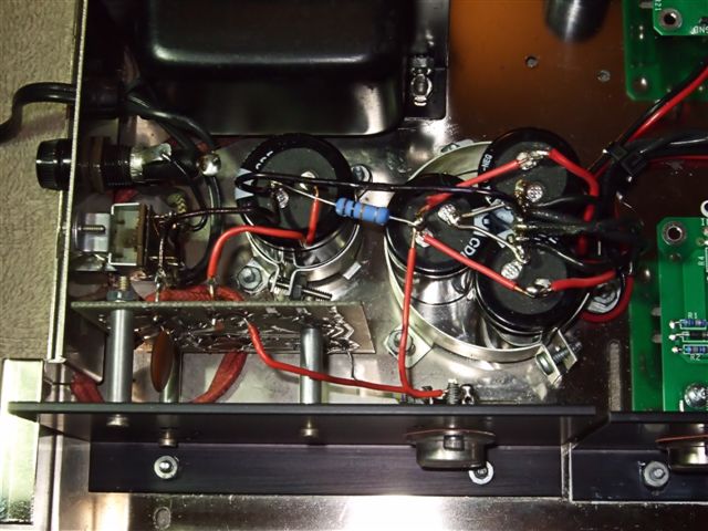
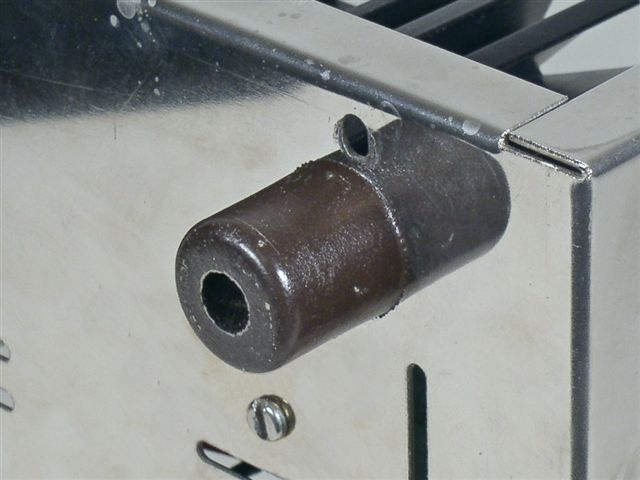
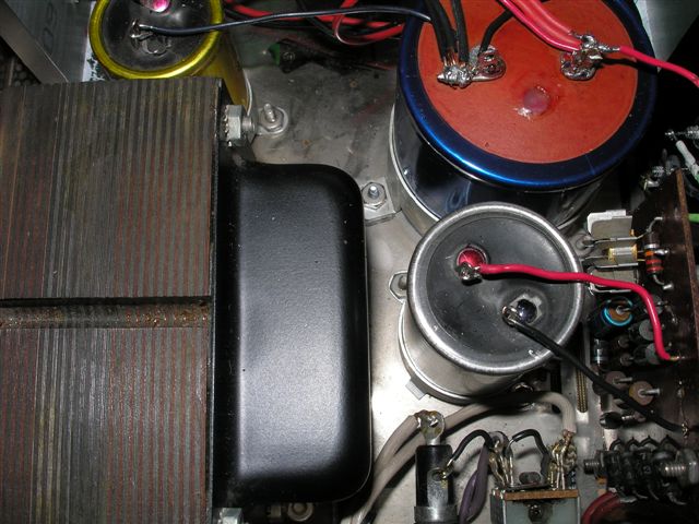
It has provided one mystery. In latter years it has experienced two wires breaking for no apparent reason, snapping off clean. One was at a lug, the other at a board, both close to the solder. I've never seen that before. So, do I get an honorable mention for the most interesting Stereo 120 experience or were they all so bad? I'm attaching some pictures showing the nifty heat sinks from my junk box and the semi star ground arrangement. Oh yes, the foot is one half of a synthetic "cork" from a wine bottle. I forget what label.
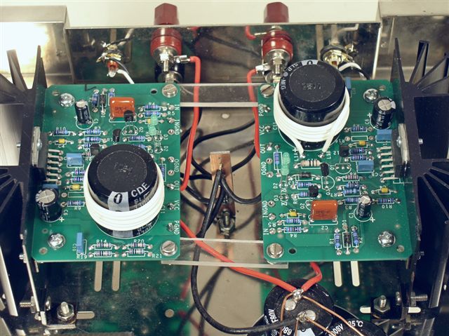
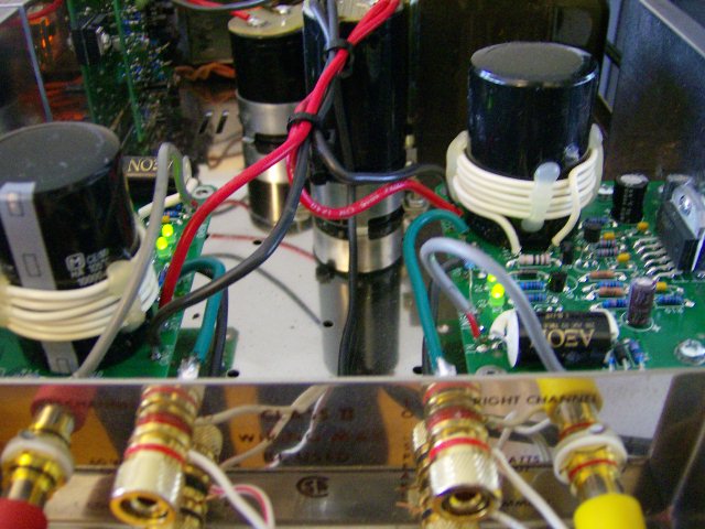
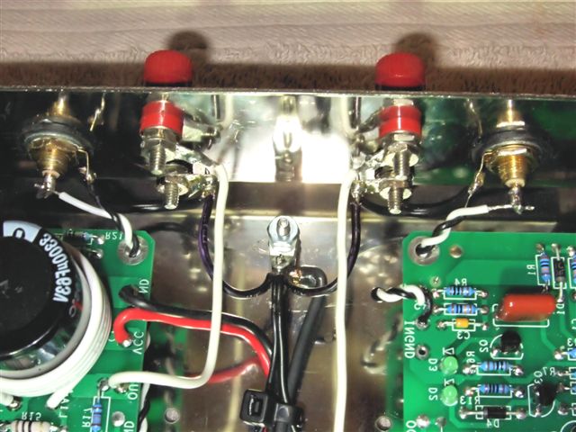
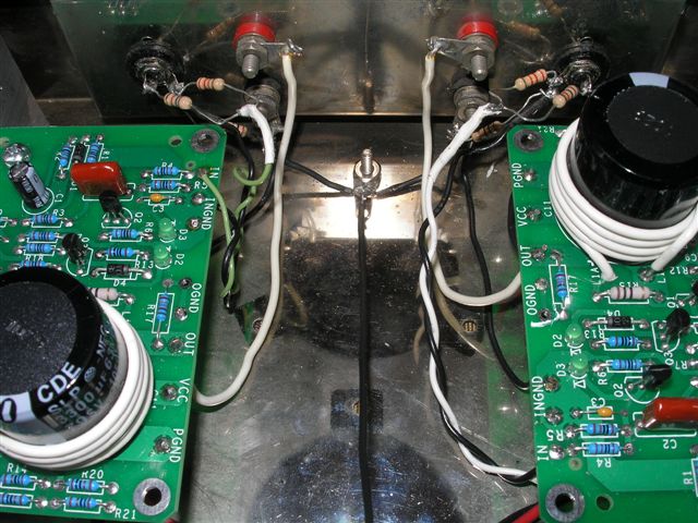
This first set of pictures comes from a customer known as "cg", granting him fame with a small "f" while preserving his privacy. Note that "cg" used the updated grounding scheme, now standard in all the directions, but also has installed isolated jacks and 10 Ohm ground loop breaking resistors. In addition, "cg" has added two resistors to each channel to decrease the amplifier's input sensitivity.
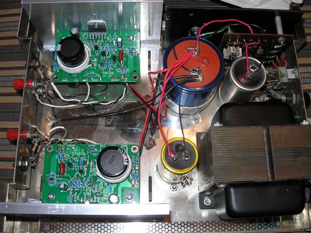
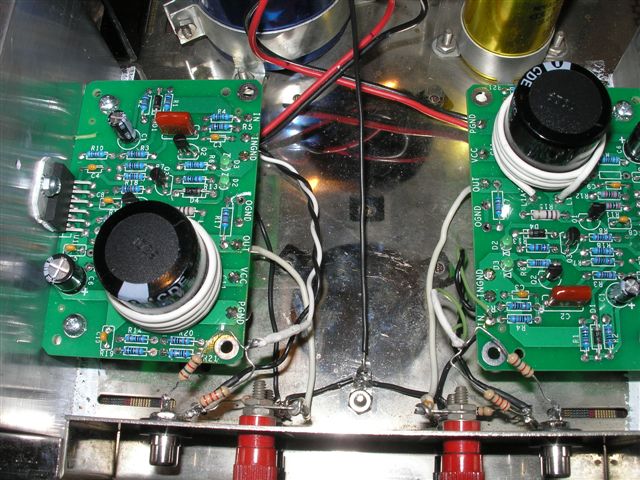
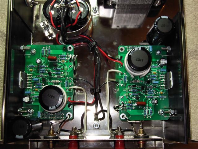
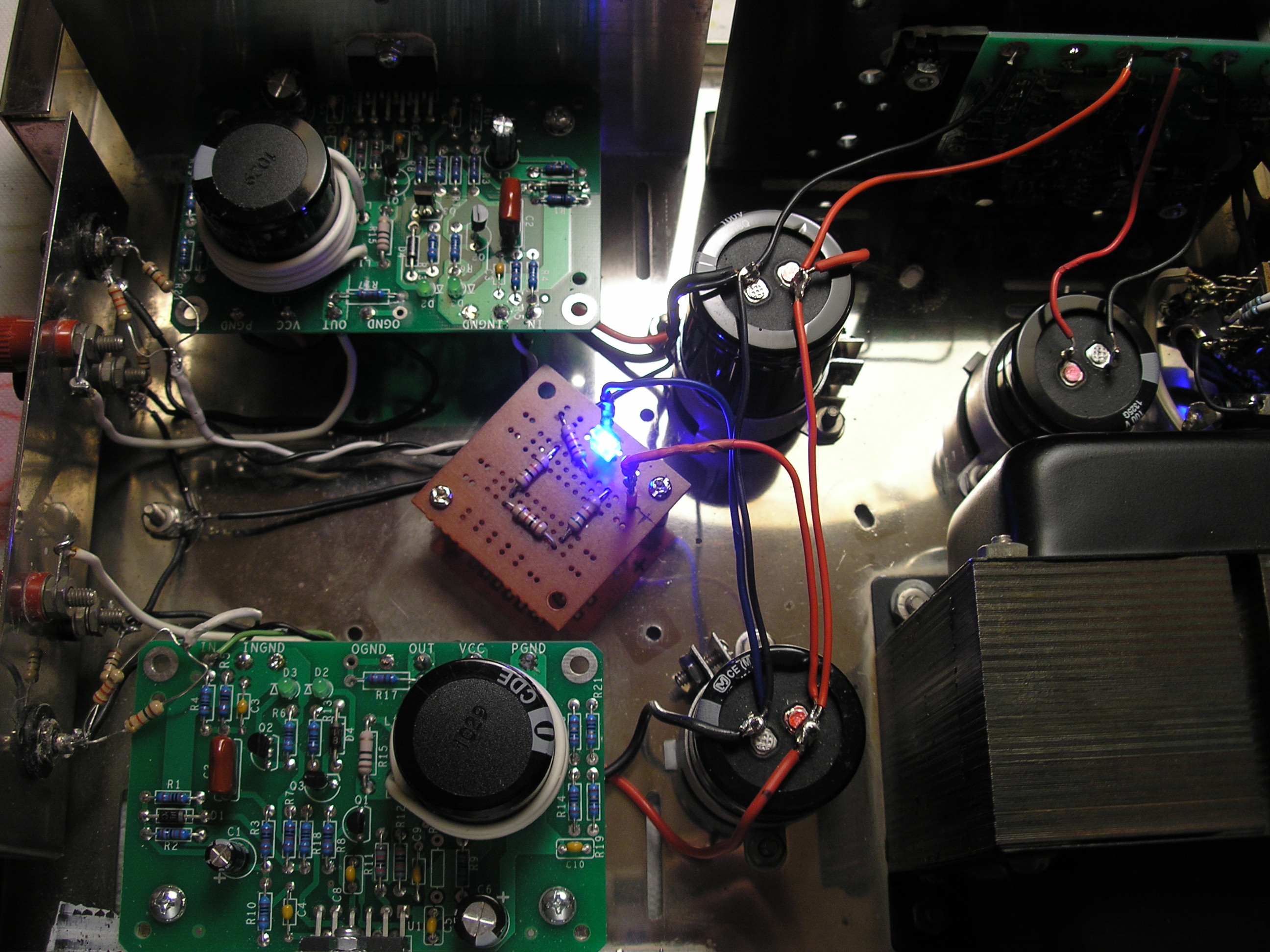
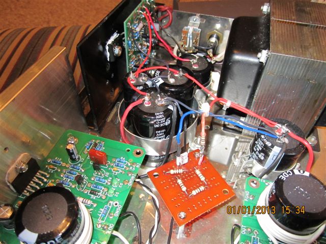
Cg later decided to add more performance, adding the PSUG (Power Supply UpGrade) kit, the PSRC (Power Supply Replacement Capacitors), a Blue Light Kit for the power switch (not shown), lots more microfarads in the power supply, e.g. more than just the PSRC, plus the general blue light that he put in the center of the chassis. In Cg's own words:
"Here they are, as promised - final pix of my Dynaco 120 with the addition of a new C12 cap (6800uF), so that the total output is 10.7KuF, enough to play every organ symphony at max volume!!! So....now I have to rename the amp: "Dynaco-Akitika Stereo 120" - the only original Dynaco parts remaining are: the case and feet, transformer, fuse and fuse holder, power switch body, PC-15 heatsink and the output-speaker jacks - everything else is yours, or the result of your idea. The blue led in the middle of the case is my idea!!"
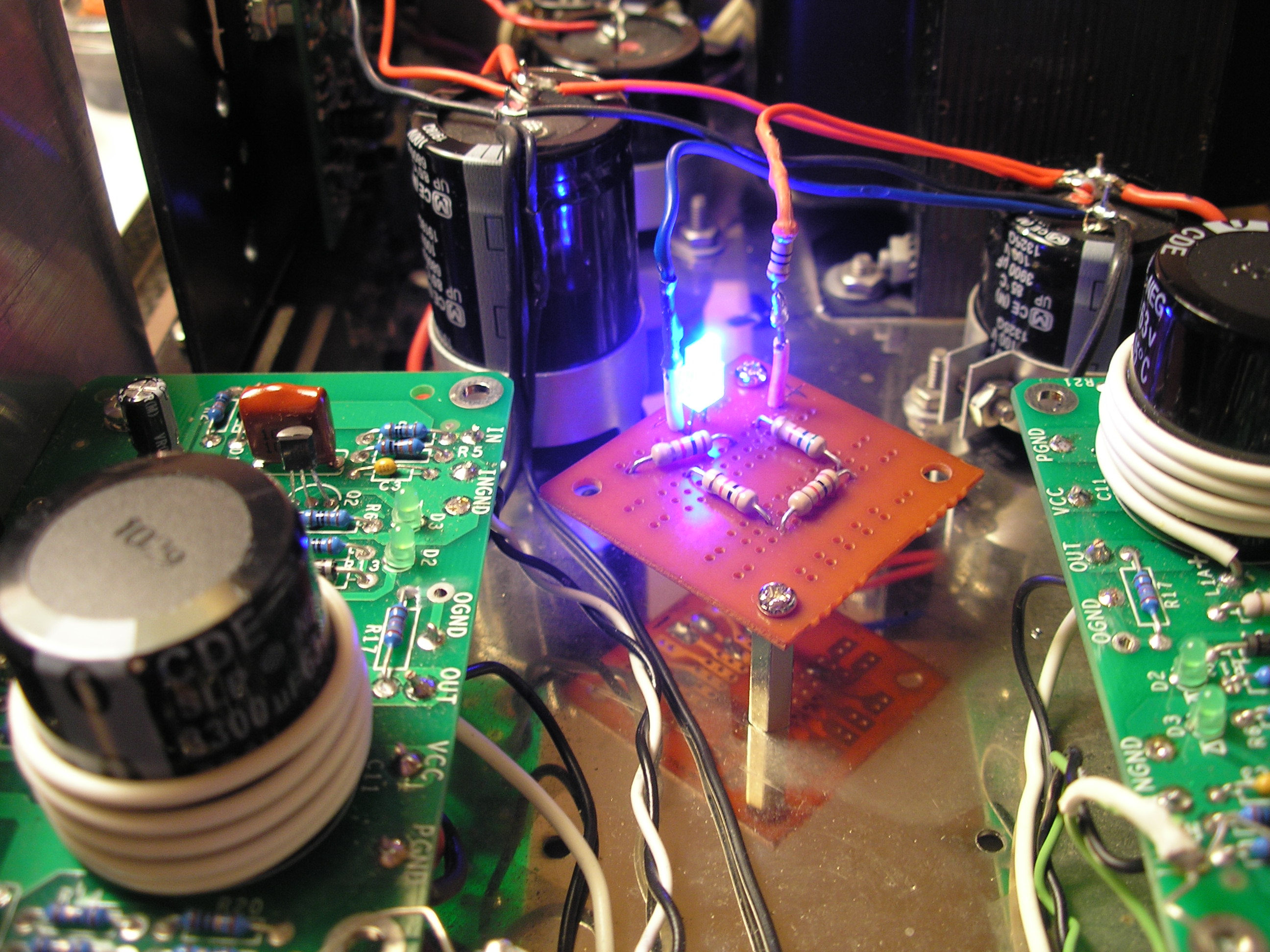
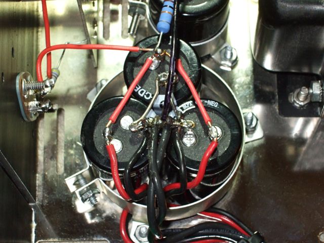
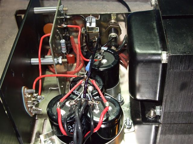
On or about New Years day 2013, CG went back into his Stereo 120 to add his own bit of dynamite...20,200 uF for C12 by CG's reckoning. You can never be too rich, too thin, or have too many microfarads!
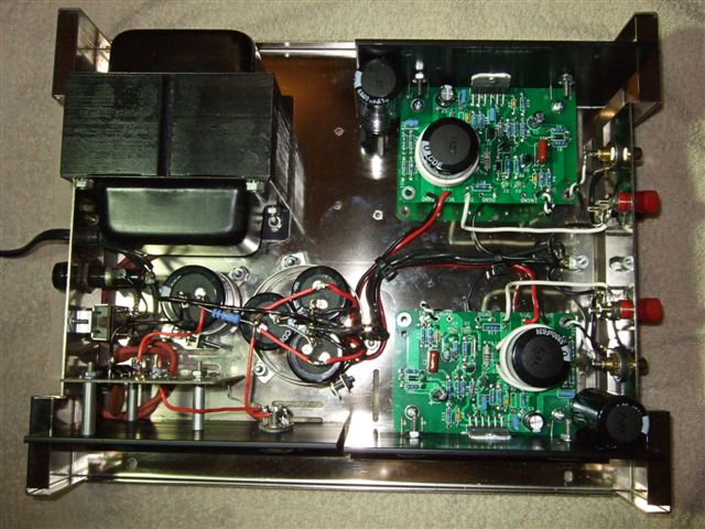
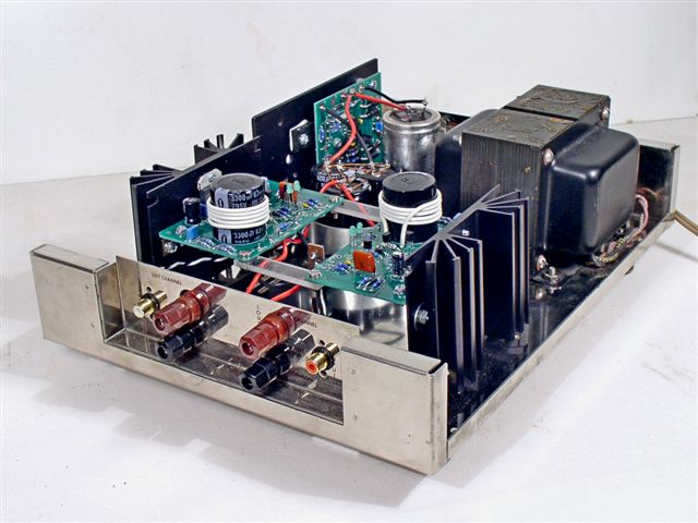
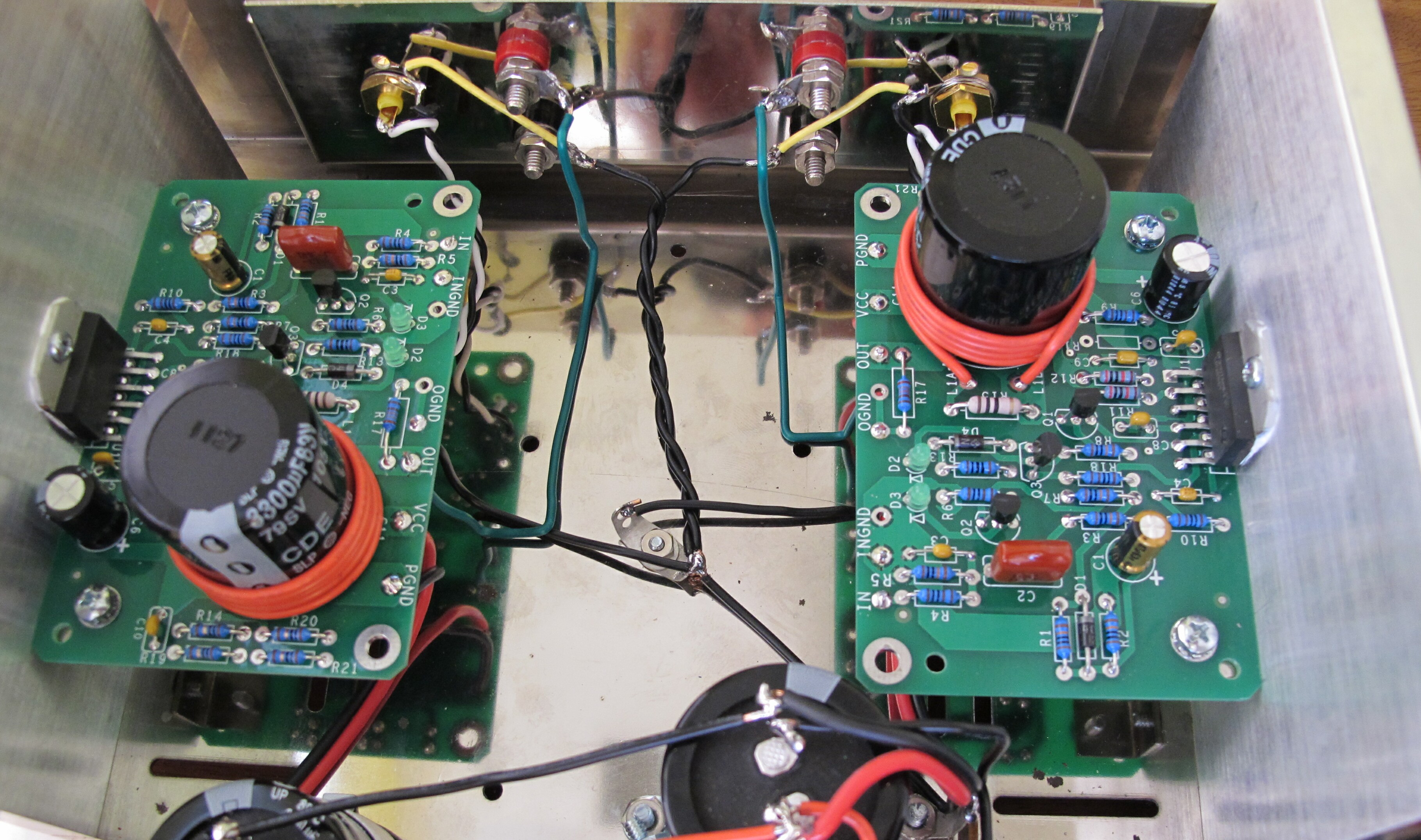
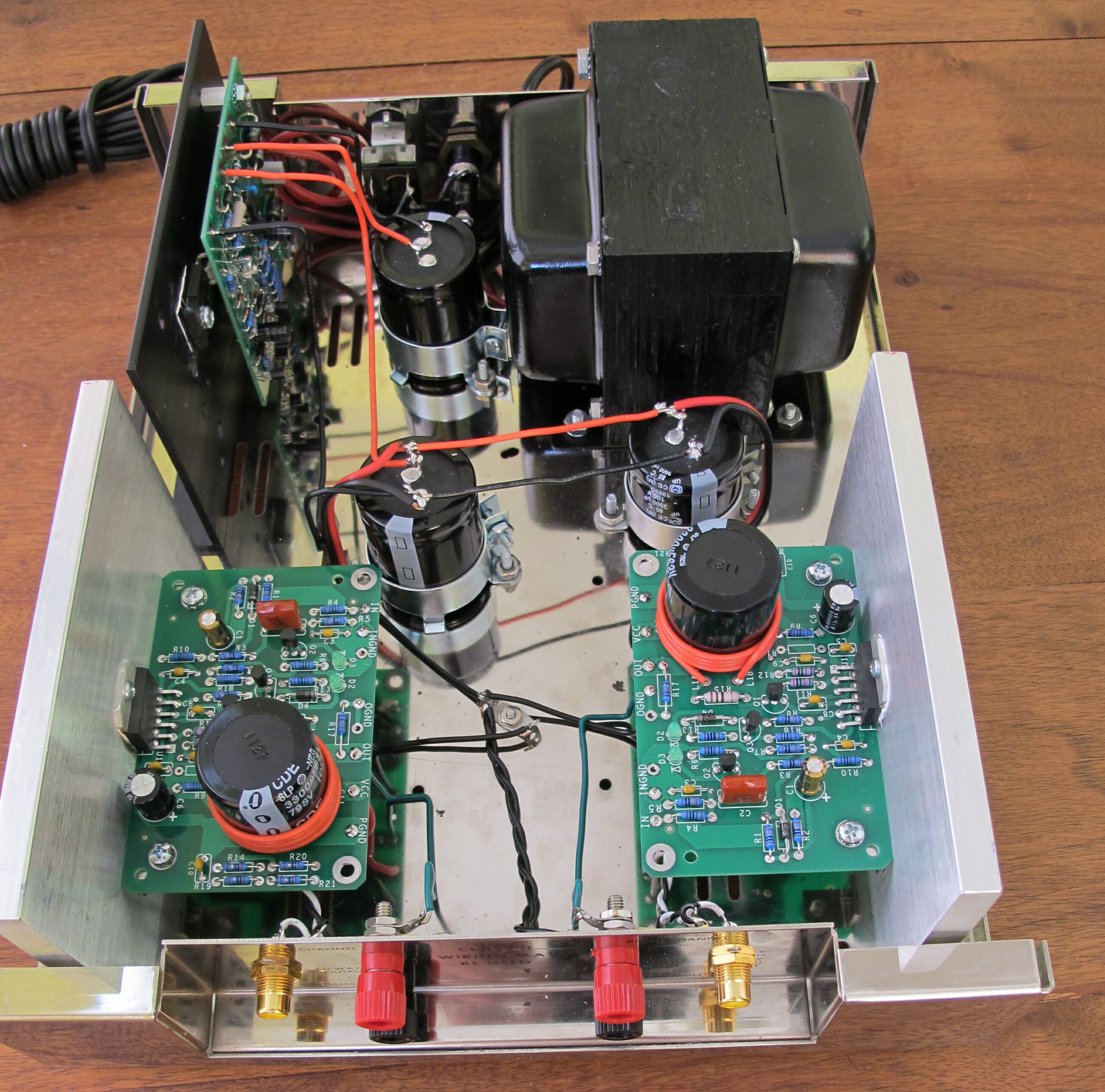
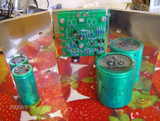
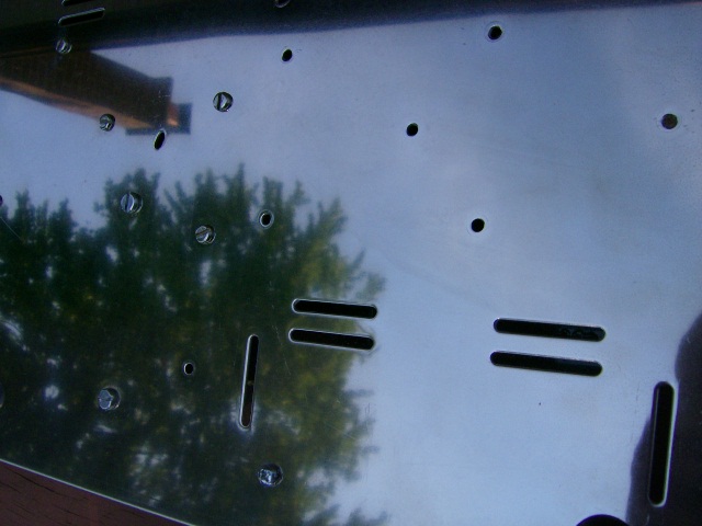
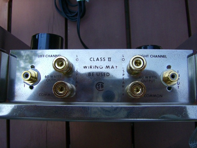
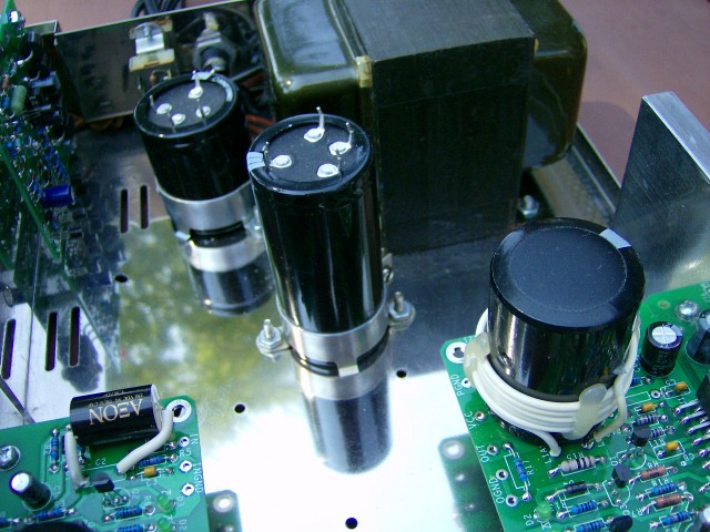
This next set of pictures comes from Bob from California. Bob sent these stunning pictures of a beautiful restoration using super heat sink (SHS), new amplifier modules (TCK), the upgraded power supply (PSUG), and one and one half power supply replacement capacitor kits (PSRC), doubling the size of the final filter to 7800 uF! He has also added gold plated input connectors, and cleaned the chassis up to a great shine! He painted the transformer with 500 degree Krylon High temp semi-gloss black. Way to go!!!"
Another beautiful restoration example comes from Mitchell, in Toronto, Canada. Mitchell polished the heck out of the chassis and the Super Heat Sinks that he ordered. Here's Mitchell's advice on polishing the Super Heat Sinks:
"Polish with 400 grit paper on a rotary sander or drill attachment using mothers alum/mag paste (use lots of paste) or just as good was compound polish (coarse) for the beginning of the process. Do this a few times (4 to 6). The polish will turn black, rub it off and repeat each time. After you are tired of the 400 grit paper method use 2000 grit paper but now use the back of your finger to push the paper around (no power tools). Use mothers paste now. Repeat, repeat, repeat. I stopped when I could recognize my face in the shine. You can get it to like a mirror finish depending how much time you want to spend polishing. On a bright sunny day I can reflect light easily 120 feet into my neighbours windows as if I was standing in front of my neighbours window with a flashlight."
For polishing the chassis, Mitchell recommends:
"For chassis use a power tool ( if it fits) or by hand use rubbing compound (coarse). Do not use sand paper for chassis. And again over and over until you get tired. Then I used Mothers chrome polish a few times to finish it off. Remember inside of chassis does not have to shine like a mirror because it will be covered. But the outside (use power tool if you have one) make it shine as best as you can. Do not rub the lettering too much or you will lose it. You have to apply the compound and wipe it off and repeat."
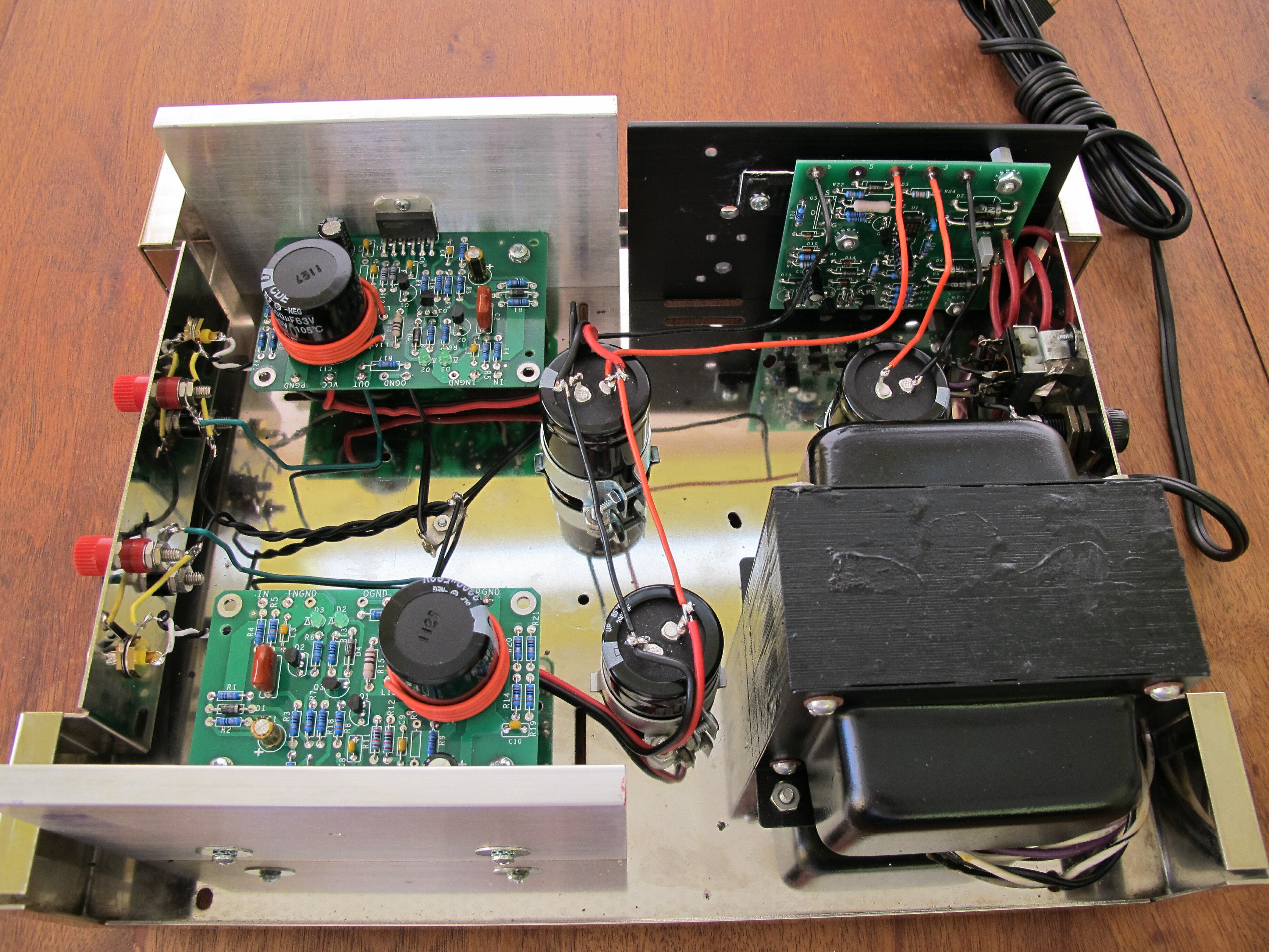
You'll note also that Mitchell bought a one more super heatsink, and drilled it out for the PSUG. He also swapped out the stock I/O connectors for some gold plated stuff that he found. Mitchell also bumped up the size of a number of the capacitors, and moved C11 a bit for a more central location (this required him to drill a few new chassis holes.
The final picture from Mitchell's rebuilt shows a bit of the wiring, extra bright LEDs (Mitchell asked for approval for a few value changes), hot glue to hold the output inductors in place (see tips for kitbuilders), and shielded cable on the input wiring. Nice job!