| Home Page | Updatemydynaco Store |
|---|
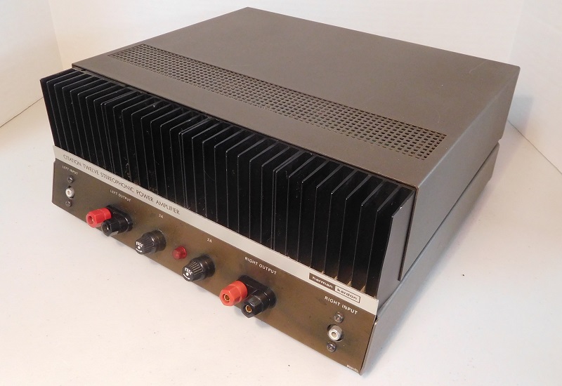
The Citation 12 was Harman Kardon's first big transistorized power amplifier. It was rated at 60 Watts per channel. It was based on a design published in the RCA Solid State Handbook. It's a relatively modern design in that it has a differential input stage. Many other things are a bit old-fashioned, like a boot-strap capacitor rather than a current source in the voltage gain stage. This was common practice in an age when transistors were still relatively expensive. The output stage used two NPN transistors, a quasi-complementary output stage.
It used separate power transformers, bridge rectifiers, and filter caps for the left and right channel. As such it was a dual-mono design. This also helped maintain the output power as the two transformers can typically offer better regulation than a single transformer.
There are big heatsinks, a thermal cut-out on each heat-sink, and a fuse for each power supply. There is no DC fault protection, so a big fault in the output stage might put up to plus or minus 41.5 volts right onto the loudspeaker. I don't think this happened often, as the Citation 12 doesn't have a reputation as a speaker killer.
I was able to buy an original Technical Manual on Ebay. I've included a
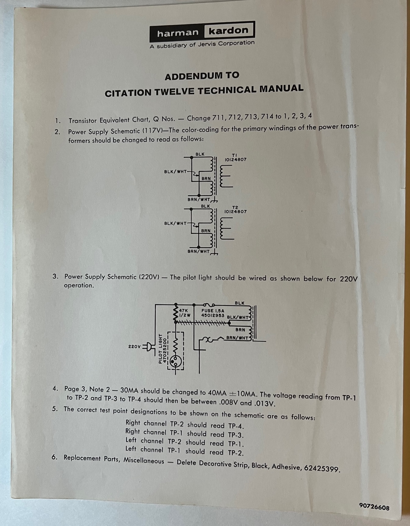
A customer sent along a later addendum to the manual. We have posted it here:
Checking my files, I found a copy of the Installation and Operation Manual:
Looking at the schematic, it refers to a number of long obsolete RCA transistors. I found copies of the old RCA transistor manuals, and have excerpted the RCA transistors.
The Citation 12 was based on an RCA design found in their semiconductor data books.
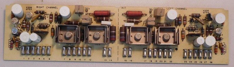
The amplifier circuit board plugs into a socket. It's retained in place by 4 screws and two plastic brackets. Both amplifier channels are on one long circuit board.
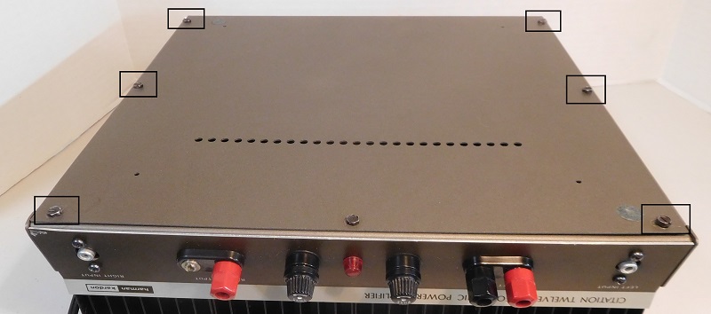
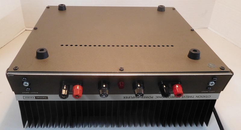
Spread a towel out on your work-bench to avoid scratching the top cover of the amplifier. Tighten your weight lifting belt, then flip the Citation 12 upside down. There are 6 black sheet metal screws (shown in the square boxes above) that hold the bottom cover plate in place. Remove those screws using a screw-driver or a 1/4" nut driver. Remove and set aside the bottom cover plate.
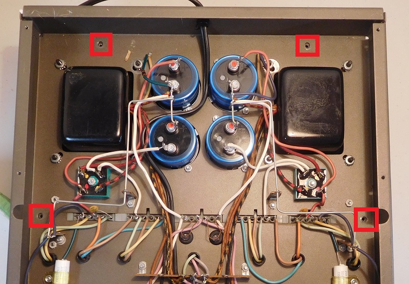
Four more sheet metal screws (located in the red squares), silver in color, hold the top cover in place. Remove these screws so that you can lift the base assembly, which will leave the top cover on your work bench. You now have service access to components on both on top and bottom of the chassis.
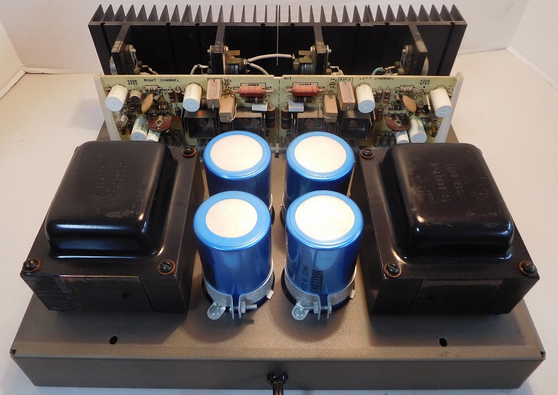
The circuit board for both channels plugs into a socket in the base. Here's a picture of that PCB.
When I received it, the amp had no feet under the bottom cover. That would allow the bottom screws to scratch whatever table the amp was placed on. There was a tiny bit of two felt bump-ons, but that wasn't nearly enough to get the job done. There are four holes in the bottom cover that take a 4-40 screw. So I used 4-40x3/8" screws, 4-40 keps nuts, and a set of FFT feet.
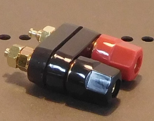
The binding posts for the right channel were damaged in shipping. I was able to find a compatible set at Antique Audio, part number S-H263. They're shown in the picture below.
I was curious about hum and noise from a Citation 12. It's not horrible, but it isn't pristine, either. I did some experiments to discover the source of the hum. Likely sources could be:
The result was that the source of the hum was magnetic coupling from the power transformers. How did I determine that? Adding 22,000 to each rail didn't help the hum. Connecting up a toroidal transformer outside the amp, and into the existing filter cap and grounding system did clean up the noise. Now, there might be a combination of mu-metal shields or steel walls that could do a similar reduction in hum, but I didn't carry the experiments that far.
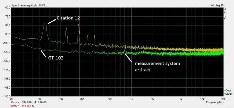
In the picture below, the upper trace is the hum from the left channel of a Citation 12. The trace below that is the hum from the left channel of a GT-102. The GT-102 has much lower hum and noise, which results from using a toroidal transformer and a steel wall and lots of space between the power supply and the amp modules.
under construction
under construction
The Citation 12 is a nice platform for improvements. We could probably drop in a modern amplifier design, and improve the distortion and signal to noise ratio. under construction
Click here to return to the home page.