Some people would rather repair their Stereo 120 without updating it, maintaining the original design. That can be difficult. We hope this web page and the hints it offers could make it easier.
Later on down the page, we show some great upgrades that let you turn your Stereo 120 into an awesome amplifier.
If the power supply doesn't work, then the amplifier certainly won't work. This white-paper contains a circuit description for the power supply and FAQs. These might help you troubleshoot problems with your power supply. If all this information seems like a bit much, you might choose instead to buy the PSUG, or Power Supply Upgrade Kit.
If your investigations show that some of your power supply caps have lost capacitance, then the PSRC Power Supply Replacement Capacitor Kit may fit the bill.
If you're looking for the ultimate in bass, then the C12XX kits may bring a smile to your face. They increase the power supply output filter cap from 3300 uF to 20,400 uF, greatly increasing the amp's ability to deliver powerful, distortion free bass.
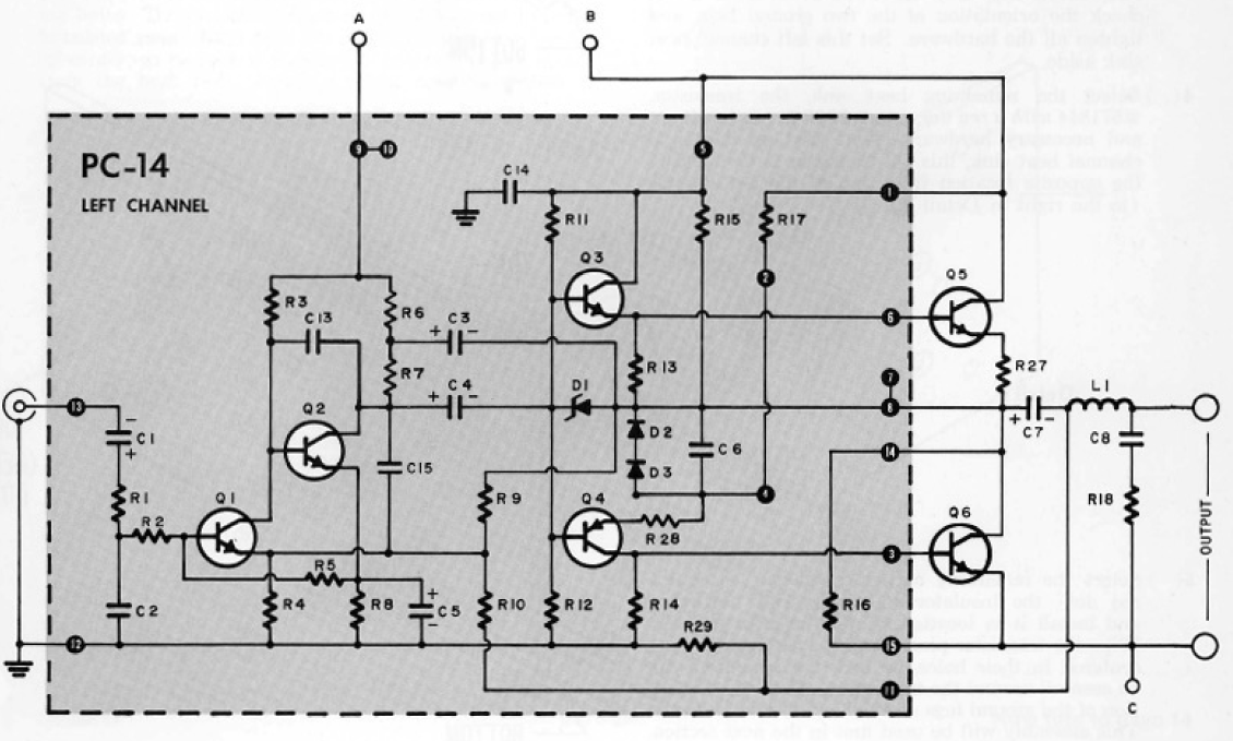
This white-paper contains a circuit description for the original Dynaco Stereo 120 amplifier module. An alternative is to build upgraded module kits.
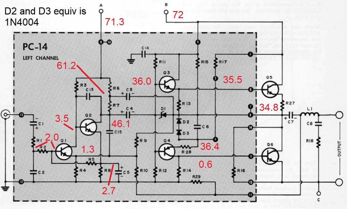
This picture shows the nominal DC voltages on a Stereo 120 Amplifier module when the amp is powered up with no signal on the input. Like all such charts, you have to have some experience to make it useful. That is, there are places where a few volt difference isn't significant...other places where 0.1 volt of difference is kind of a big deal. Here are some examples
Of course, repairs are much easier to do with the schematics and parts lists as shown in an original assembly manual. The pdf files below are high resolution scans of an original repair manual, and include the later schematics with their additional components.
The Stereo 120 was in production a relatively long time. Changes were introduced throughout that production to make it better and/or more reliable. You can track the changes by the component numbers. For example the R numbers were added sequentially as resistors were added in the course of production history. I reviewed 5 or 6 Stereo 120 Assembly manuals that I have, and have reconstructed a history of the improvements.
It may be worth looking carefully at your amp. If it has original modules and it isn't working, then it's possible it died from the lack of the above cited modifications. You could repair it, or you could consider the update kit.
If there's no output or small output, but the power supply voltages are normal, and there's no abnormal heat or smoke, the output capacitor, C7, may have opened up. After 40 years, this can certainly happen. Even if the cap didn't open, it may have lost capacitance. The straightforward way to tell is to disconnect the capacitor, and measure it on a capacitor bridge. If you have one, consider yourself fortunate, and you can probably stop reading. But then again, what if you could test the output capacitor without de-soldering anything? To do this test, youll need:
Proceed at your own risk. The amplifier, when open, exposes DC voltages of up to 100 Volts, and AC voltages of 120 Volts RMS (240 Volts RMS) in some cases. Please work safely. Keep one hand in your pocket as you probe.
I wont belabor all the steps. Instead, Ill just give the big picture. Of course, youll have to remove the cover to get access to the capacitor leads. For a given channel and capacitor:
C7(uF)=5000/V7, where V7 is in volts
If you find that C7 is a bit low, or if you just want better bass, you may find the C7X2 kit of interest.
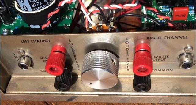
Sometimes people like to just pair a Stereo 120 with a CD player. Other times, they'd like to change the sensitivity of the Stereo 120 to put the accompanying preamp's volume control
into a better range. You can accomplish both of those by adding a volume control. I suggested installing the VC102 Kit between the I/O connectors to a customer, Richard. It worked out
very nicely, and Richard was kind enough to send along pictures of the result.
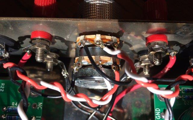
You'll note that the VC101K comes with plenty of shielded cable, but it's not really needed for this application. The placement is so nice that the volume control wiring is quite short. Twisted pairs do a good job.
Pick just the parts you need at the Updatemydynaco Store to bring your Dynaco Stereo 120 Power Amplifier back to life, to improve it a bit, or to take it about as far as you can go.
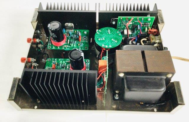
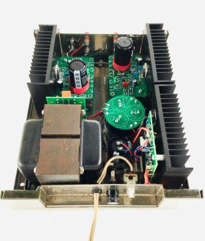
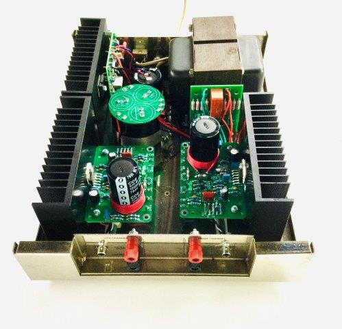
John M, a long-time customer was kind enough to supply these pictures of a full monte Stereo 120 upgrade. This upgrade uses:
Just got to share this with all you audiophyllum out there--If you are interested in improving the sonic quality of your stereo system--I've been around stereo systems and components since the mid 60's, sold them, built several complete Heathkit stereo systems, am a classical and contemporary musician and piano tuner, and i think i am a fairly good judge of "quality" sound, or, at least what pleases my ear.
My present stereo system consists of the UpdateMyDynaco 120, the Hafler 915 FET preamp, old Pioneer 10X 3-way speakers, to which i have added in parallel to the speakers a 5" midrange and the Radio Shack film tweeters in series, and 2 car stereo 6 X 9" speakers in series, out of phase w/each other across the positive connections of the amp channels for the "Hafler Effect" for ambience.
In 1985 i was given a Dynaco 120 amp, which i have used up til now. I recently came across Dan Joffe's info online about the Updated version for the Dynaco 120, and thought it might improve the overall performance of my system, besides the fact i just love building electronic kits. WELL !---- Besides a couple "minor" boo-boo's" on my part, like mixing up the installing of 2 resistors w/each other but which were quickly rectified with the VERY patient and efficient help from Dan-i finished the assembly process and gave a listen.
WOW !! I was BLOWN AWAY! Total sonic clarity and balance at ANY volume level--NO shrillness or brittleness in the treble, and tight, full bass, with ABSOLUTELY NO boominess. I could DEFinitely hear the difference that removing the crossover distortion that was in the old Dynaco 120 i had makes. And the bass response, as well as the overall clarity was greatly improved.
I have been around all kinds of public music performances in my 72 years, including sessions in recording studios, and i honestly have never heard anything that sounded any better in portraying the ACTUAL sound of the LIVE performance--if i close my eyes while listening, it's not hard to imagine the instruments and voices are right in my room. Without using descriptions, it just sounds REALLY GOOD !
I can't recommend this updated version of the Dynaco 120 highly enough. And Dan Joffe provided the BEST customer service of ANY venue i have EVER experienced, bar none. I was not paid or requested to give this testimonial. I'm just a VERY satisfied customer, giving my honest opinion of what i consider i very high quality product @ANY price.
Rich from Baldwinsville, NY
A customer assembled and installed the TCK (updatemydynaco amp modules) and a PSUG into the Stereo 120. Along the way, he tried to reduce the mechanical hum of the power transformer by mounting it up off the chassis on grommets. I'll make a long story short...Don't mount your power transformer on grommets!
The Dynaco transformer has beefy E-I laminations. In the stock arrangement, those laminations rest directly on the steel of the chassis. This confines the leakage flux very nicely. If you raise the transformer off the chassis, there's a good sized air gap which lets a lot of the flux density travel. In this customer's mod, the left channel board ended up in a flux hot-spot. The right channel was in a nice null. The confusing result was that even with the recommended grounding scheme implemented, the right channel was dead quiet, and the left channel hummed.
Eventually, we figured out the problem described above, dropped the transformer back down onto the chassis, and now both channels are quiet.
At some point, we might even further reduce the stray (leakage) flux with a "Belly Band". A quick experiment with a bit of aluminum foil seemd to show a 3 dB improvement. As time permits, we should revisit the Belly Band in a more official way, with copper foil.