After 40+ years, the power supply capacitors in a Stereo 120 may lose capacitance, bulge, increase their ESR, short, or otherwise just become candidates for replacement. Those caps are:
We know that you guys are busy, so we'll start with what we believe are the best answers. We'll follow it up with some of the reasoning behind those suggestions. If you'd like to see a video with the overall idea first, take a look at this:
The single most important thing you can do for better bass is to replace C12, a 3300 uF cap, using one of the C12 replacement kits. There are 4 different kits, each one tailored to the four possible combinations of power supply and amplifier modules in a Stereo 120.
The replacement kits all supply three 6800 uF caps, for a total of 20,400 uF. Their diameter is chosen so that they fit together in a dynamite configuration, and mount conveniently into the same 2.5" diameter clamp that held the original 3300 uF capacitor.
Buy the C12 replacement kit.
Read the Installation Manual for the C12 replacement kit.
Yes, you'll get better bass. But there's another interesting demonstration of how much energy the C12 upgrade holds. The following video demonstrates just that.
We can use the triple capacitor configuration to update and upgrade the output coupling caps, C7. We'll make the assumption that if you're reading this, you want more than just a 1 for 1 capacitor replacement.
The original cap value was 3300 uF. The C7X2 kit pushes this up to 9900 uF using a triple arrangement of 3300 uF caps. This decreases distortion at the lowest frequencies. The C7X2 kit contains:
The original cap value was 3300 uF. The CSU2 kit pushes this up to 10000 uF in one capacitor. You just swap it out for the existing capacitor on the PC Board. This change decreases low frequency distortion, while completely avoiding sub-sonic peaking owing to the design of the updatemydynaco amplifier modules. The CSU2 kit contains:
C12, the power supply output filter is 2.5 inches in diameter. Quite frankly, they don't make appropriate cost and value capacitors in those large diameters any more. You could buy new mounting clamps to mount smaller capacitors, but they're hard to find. There's an alternative.
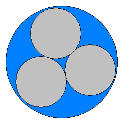
I call it the Dynaco Dynamite Capacitor Configuration. Take three capacitors and pack them together. It's an interesting math problem. What is the diameter do of the outer circle that surrounds three closely packed inner circles, each of diameter di? It turns out that the ratio of the diameters is 1+sqrt(3)-1/sqrt(3), which is equal to 2.1547.
Consider C12, the power supply output filter capacitor. It's 2.5 inches in diameter. If we replace it with three capacitors in a "dynamite" cluster, each capacitor should have a diameter of 1.16 inches, or 29.47 mm. That's within 2% of 30 mm, a standard capacitor diameter. So, we could replace C12, a 2.5 inch diameter capacitor, with 3 capacitors, each one 30 mm in diameter. We can put them in parallel, and get a lot of capacitance, but how much is too much? We'll check that out a bit later.
C7, a speaker coupling capacitor (there are two, one for left, and one for right channel) has a diameter of 2 inches. If we replace it with a cluster of three capacitors, each one would have a diameter of 2/2.1547=0.9282 inches, or 23.58 mm. That's within 6% of 25 mm, another standard capacitor diameter. That's still close enough that you can hold 3 25mm diameter capacitors in the 2 inch capacitor clamp that held C7. Once again, if we put them in parallel, the result could be quite a lot of capacitance. So...how much capacitance is safe?
How much capacitance can we use? C12's original value was 3300 uF. So, one easy answer would be to use 3 caps of 1000 uF each. That's not that much fun. Can we go bigger? Using the standard Dynaco regulated power supply board, I'd recommend staying at or below 3x1500 uF. The issue is the start-up transient might challenge the SOA (Safe Operating Area) of the pass transistor. However, if we change C10 from 50 uF to 270 (or more) uF, we slow the startup enough to safely increase C12 to 3x6800=20,400 uF!
The PSUG (Power Supply Upgrade) can accommodate up to 20,400 uF for C12 with no other changes.
The stock output cap was 3300 uF. It was wrapped in a feedback loop to make it appear twice as large. Perhaps with a dynamite capacitor configuration we could go pretty crazy here. I did some simulations to see if increasing the output capacitor size would have any ill effect on low frequency stability. If anything, it made the low frequency response flatter, with no bad side-effects.
The other possible downside from a much larger value for C7 is that there's a bit more potential SOA stress on the output devices. With a smaller cap, even if you short the output to ground, the output current is time limited by the capacitance in addition to the built in limit from the zener diode. Still, no guts no glory! I think that while 3x1000uF=3000 uF is a conservative choice, 3x3300=9900 uF would probably be alright, but you should be quite careful not to short the output of the amplifier. Some of these things are difficult to say definitely since the output devices were specially selected for Dynaco, even though they had nominal 2N numbers. The only time this should be an issue is if you short the amp's output to ground while it is being driven with a low frequency signal.
The C7X2 kit supplies everything you need to replace both C7's in a Stereo 120 with original amplifier modules. Take a look at the C7 replacement manual for more details.
Now, in the GT-101 amplifier, we use 10,000 uF output capacitors. The output amps have adequate SOA protection that large output caps are perfectly safe.
The original inductor is 74 inches of 16 AWG insulated solid wire wrapped around C7, a 2" diameter capacitor. Using the Wheeler formula, that calculates out to about 5 uH or so. Actual measurements show a lot closer to 1.0 uH. What's going on? Recall that the coil is wrapped around the cap. The cap consists of two rolled up conductive sheets separated by a dielectric. It looks like a loosely coupled one turn secondary to the primary of the speaker inductor wrapped around the cap. That reflected impedance drops the inductance, making it much less than you'd expect. I took network analyzer measurements and fitted a model in the region from 1kHz to 10 MHz. The model looked like this:
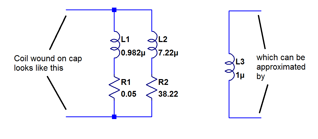
As a result, we need to figure out how many turns of wire we should place around the dynamite capacitor configuration to get back to around 1 uH. We might need fewer turns since each turn is more loosely coupled to the "shorted turns" of the capacitors. Analytically, the problem might be sticky. Perhaps a lab measurement would be a lot quicker! We did that and found that 5 turns was about right. That puts less than half as much wire between the amp's output and the speaker. That's about 3 feet less wire!
C9 and C11 both have a diameter very nearly 35 mm, which is a modern day standard capacitor size. C9 is the main filter for the bridge rectifier, with a nominal value of 1000 uF. You could bump this up to a maximum of about 3900 uF without causing any trouble. It would drop the ripple into, and hence out of, the power supply. It might also help a bit with instantaneous low frequency power.
C11 is 500 uF nominally, and performs filtering for the driver stages of the amplifiers. It's required with the original amplifier modules, but isn't necessary with the updatemydynaco amplifier modules (although it can be paralleled with C12 in the case of updatemydynaco modules). 1000 uF in C11 might result in slightly more power at low frequencies as it would hold up the driver stage a bit longer even if the main output voltage sagged a little bit.Of course, you could go still higher if you change C10 to 270 uF or more in the original Dynaco power supply. As mentioned earlier, that change limits the turn-on current, keeping the pass transistor healthy. We make those changes in the Extreme kits.
Everything has limits. The power a transistor can dissipate is limited by something called Safe Operating Area, or SOA. It's a family of curves that show how much power can be dissipated for a given length of time. Such curves show that while a transistor might safely dissipate heroic amounts of power for a millisecond, that same transistor might safely dissipate much less power for 100 milliseconds, or a second, or continuously.
The most strenuous time for the power supply pass transistor, Q9, is during turn-on. At that time, the output filter caps are being charged. The combination of voltage across and current through the pass transistor is at its worst. For that reason, we've slowed the power supply's rise time by changing the value of C10. That dramatically drops the charging current during turn-on, limitng the current to one within the SOA of Q9.
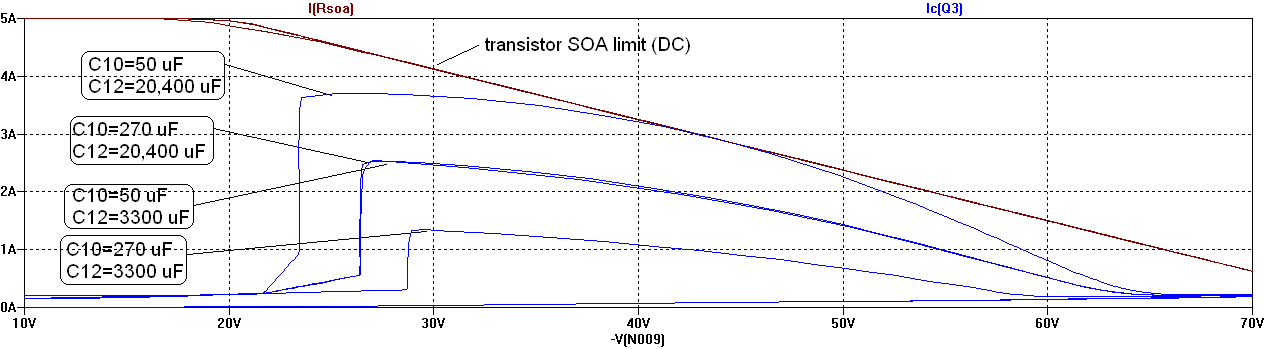
The curves show that increasing C12 without increasing C10 would cause us to collide with the SOA limit. Increasing C10 to 270 uF makes the SOA the same with 20,400 uF as it was with 3300 uF, insuring long life after the modification. The 330 uF value we supply in the kits for C10 just makes things even safer. The bottom curve shows that you could get an extreme amount of SOA margin if you increase C10 to 270 uF while maintaining C12 at 3300 uF.
The power supply regulator essentially has a current limit. It varies with device characteristics, put let's just pick a number of 3.5 Amps for now. That says that up to 3.5 Amps of load current, the power supply is constant voltage, after that, the output current is limited to 3.5 Amps, and the output voltage drops with increasing output current. If the output voltage drops below about 50 Volts, the power supply current drops a lot more, and the the voltage drops quickly. The power supply stays in that state until the overload is removed.
The peak of a 20 Hz 20 Volt RMS signal draws a peak current of 20*1.414/8=3.53 Amps. The average current is much less, at 0.45*20/8=1.125 Amps. So with a 3300 uF C12, the power supply can deliver (much more) than the average output current, but not quite the peak current demanded by the 20 Hz 20 Volt RMS signal. The situation is even worse if both channels are simultaneously driven. (The fine print of the old Dynaco reports showed that power measurements with both channels driven were made with out-of-phase drive, separating the peaks of output current demand.) C12 moothes out the peaks of output current, and at 3300 uF does a pretty good job above 100 Hz. By 20 Hz, it's quite a bit less effective, and so the output power suffers a bit. The really large C12, 20,000+ uF, smooths out the demand even down to 20 Hz, allowing more power to be delivered.
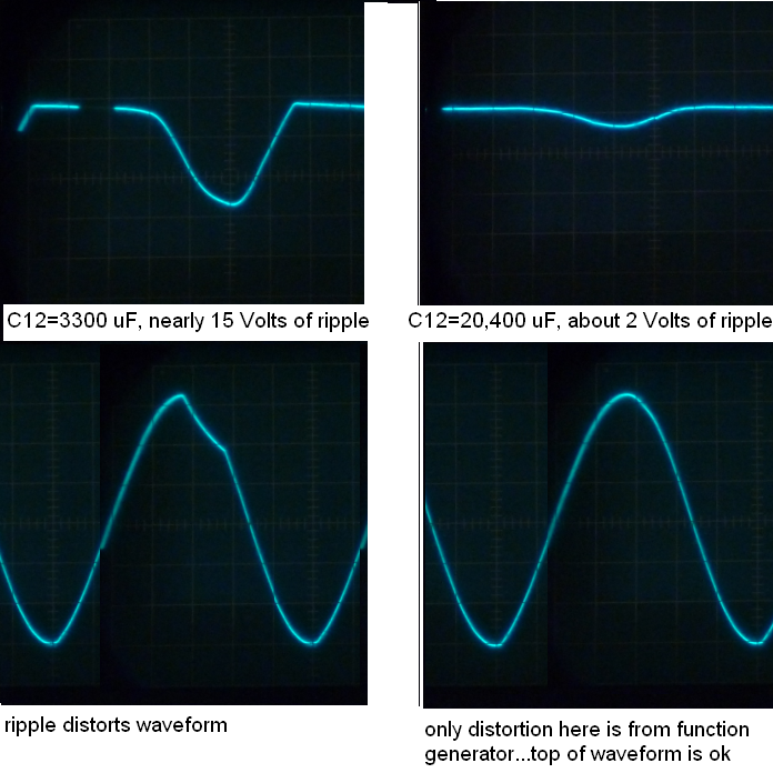
We took a few scope photos of the power supply ripple voltage. The first photo was taken with both channels driven in phase at 20 Hz and 20 volts RMS into 8 Ohm loads. Note that with C12=3300 uF, the output voltage sags nearly 15 volts. The output waveform shows significant and visible distortion.
The next photo was under the same conditions, except C12 was increased to 20,400 uF. The supply voltage ripple drops from nearly 15 volts to about 2 volts. The visible distortion in the top of the output waveform is now gone. (Note: these measurements were made with a single trace scope, and pieced together in what I assume to be the correct alignment of output and power supply ripple).
You can order the C12 replacement kits today. The PSRC kit has been available for quite some time. The C7X2 kit is ready to order,
and the manual is available, too. Just take a trip to the Update My Dynaco Store.
All the best...
Dan
Return to the updatemydynaco Home Page
![]()